Back

AMPPAL 20/30/40kW Wall-Mounted DC Charging Station

No items found.

20/30/40kW Wall-Mounted DC Charging Station

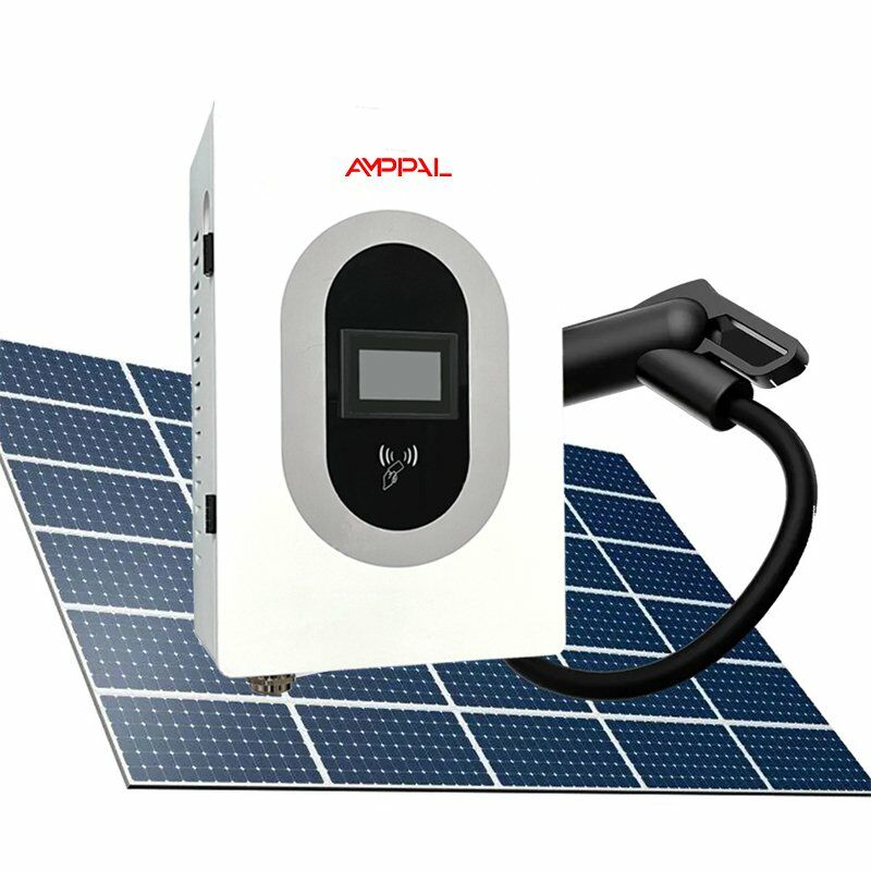
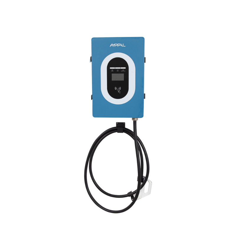
The Integrated DC EV Charger Station is suitable for city-specific charging stations ( Bus, taxi, official vehicle, sanitation vehicle, logistics vehicle, etc. ) City public charging station ( Private car, commuter car, bus ) Various parking lots in urban residential quarters, shopping plazas, power business places, etc.; Inter-city expressway charging stations and other occasions that require DC fast charging, It is especially suitable for rapid deployment under limited site conditions.

Model No. AF-DC-20-B/L-A-O-2/3/4/5-H AF-DC-30-B/L-A-O-2/3/4/5-H AF-DC-40-B/L-A-O-2/3/4/5-H
Home and Commercial Use
Specification Rated Power 20 kW 30 kW 40 kW
Charging Device Installation Method Wall-mounted / Floor-stand mounted
Feeding Method Bottom in and out
Equipment Dimension 450 × 660 × 240 mm
Input Voltage AC380V ±15%
Input Frequency 50 ±10 Hz
Output Voltage 200–(750)1000 VDC
Single Gun Output Current CCS2: 0–67 A CCS2: 0–100 A CCS2: 0–133 A
Cable Length 5 m (optional)
Metering Accuracy Level 1.0
Electrical Indicators Current Limit Protection Value ≥110%
Voltage Stabilization Accuracy ≤±0.5%
Current Stabilization Accuracy ≤±1%
Ripple Ratio ≤±0.5%
Efficiency ≥95%
Power Factor ≥0.99 (above 50% load)
Harmonic Content (THD) ≤5% (above 50% load)
Functional Design HMI 4.3-inch high-brightness color touch screen
Charging Mode Plug & Charge / Automatic full charge / Fixed energy / Fixed amount / Fixed time
Charging Method NFC (Swipe to charge), Scan QR code to charge, Password
Mode of Payment RFID, Scan QR code, Credit card, Password, APP
Network Ethernet, 4G, LTE, Wi-Fi 802.11 b/g/n (Optional, 2.4/5 GHz)
Safety Design Operative Norm EN IEC 62196-1:2022; EN IEC 62196-3:2014; EN IEC 61851-1:2019; EN IEC 61851-23:2014; EN IEC 61851-21-2:2021; EN IEC 61000-6-1:2019; EN IEC 61000-6-3:2021; TÜV (DIN SPEC 70121/12.14, DIN SPEC 70122/11.18)
Safety Function Charging gun temperature detection, over-voltage protection, under-voltage protection, overload protection, short circuit protection, grounding protection, over-temperature protection, low-temperature protection, insulation monitoring protection, polarity reverse protection, lightning protection, emergency stop protection, leakage protection.
Environmental Indicators Working Temperature -35 ~ +55°C
Working Humidity 5%–95% non-condensing frost
Working Altitude ≤2000 m
Ingress Protection IP54
Cooling Method Air-cooled
Noise Control ≤60 dB
MTBF 30,000 hours

Protection Functions

  • Input and output of the EV charger station are electrically isolated.
  • The output includes a back-feed prevention device to stop the vehicle battery pack from charging the charger’s output filter capacitor and to prevent instantaneous high current at the charger’s output terminal when the battery pack is connected.
  • Specify the charger’s voltage rating and insulation class; ensure compliance with applicable “Electric Vehicle Conductive Charging Device” regulations.
  • Designed and manufactured according to IEC 61851-1:2017 and IEC 62196-2:2016.

Check the packing box for the following items before installation (Subject to the packing list)

  • Wall-mounted type EV DC charging station (1 set )
  • Test card 2 pieces (with a card reader or not)
  • Installation instructions (1 set)  
  • 1 piece of certificate of quality
  • Key (2 pieces )

Installation Environment Requirements

  • This series EV DC charging station is the outdoor type, Ingress Protection: IP54;
  • Ambient temperature  -20℃to +50℃;

Installation Method

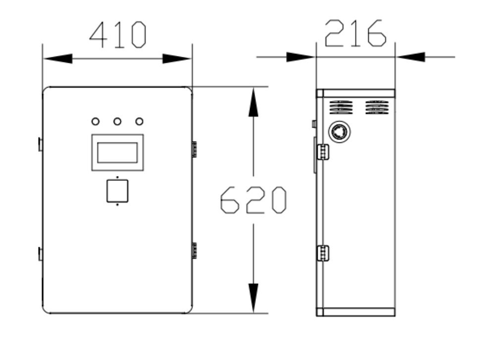
This series of DC charging stations can be installed vertically according to the requirements of Installation size, as the Figure:

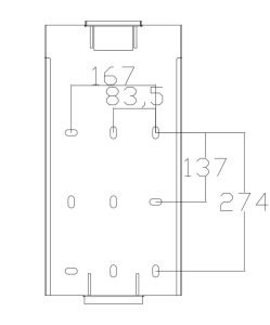
Using 12 large impact drills to punch 6 holes and plug in 10 large expansion screws.

The bottom is fixed with M4*12 bolts.

Symptoms of common faults of the indicator lights on the module panel

There are three indicator lights on the module panel, which are the power indicator (green light), the protection indicator (yellow), and the fault indicator (red), and the fault indicator is as follows:

Indicator Light Normal Status Abnormal State Abnormal Problem
Power Indicator
(Green)
On Off No input voltage; module’s internal auxiliary power supply does not operate
Protection Indicator (Yellow) Off On AC input overvoltage, undervoltage, or overtemperature
Off On Communication interruption or manual mode
Fault Indicator (Red) Off On Output overvoltage, module address duplication, or severe current imbalance
Off Flashing Faulty fan
Note: When the module is in manual mode, the yellow light flashes.

Back

Contact for Services

By submitting this form, you agree to our Privacy Policy
Thank you!
We will respond to you as soon as possible
An error occurred. Please try again later or contact us via email or phone.